- 您现在的位置:买卖IC网 > Sheet目录181 > 2938811 (Phoenix Contact)PWR SUPPLY 10A 100-240AC 12VDC
Power Supply, Primary Switch Mode for Universal Use – QUINT 12 V DC/10 A
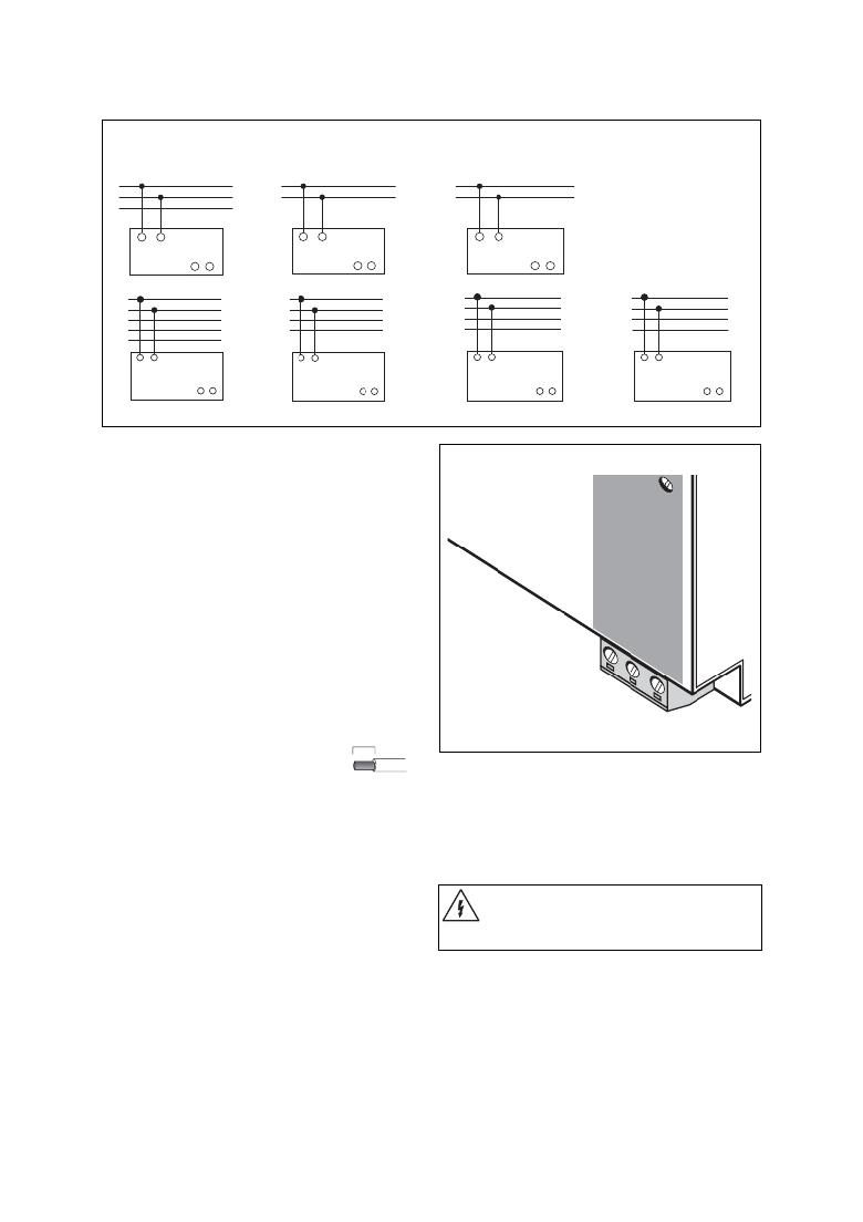
6.4. Connection of Various Types of Network: 100 - 240 V AC Networks
TN-S network TN-C network TT network
IT network
L
N
PE
L
PEN
L
N
MINI
MINI
L N
MINI
QUINT
+ –
L N
QUINT
+ –
L N
QUINT
+ –
L N
L1
L2
L3
N
PE
L N
L1
L2
L3
PEN
L N
L1
L2
L3
N
L N
L1
L2
L3
PE
MINI
QUINT
+–
MINI
QUINT
+–
MINI
QUINT
+–
MINI
QUINT
+ –
Figure 09
Connection Cable:
18 t
The device is equipped with COMBICON
connectors. This reliable user-friendly connection
method enables quick device connection and safe
isolation of the electrical connection, if required.
Only operate connectors when the power is
switched off.
To maintain UL approvals, use copper cables, which
are designed for operating temperatures of
75°C (167°F).
V
AC In
L 0 -2 t
0V
The following cable cross sections can be connected:
Solid Flexible AWG Torque
[mm 2 ] [mm 2 ] [Nm] [Ib in.]
1 Input: 0.2 - 2.5 0.2 - 2.5 25 - 14 0.5 - 0.6 4.4 - 5.3
2 Output: 0.2 - 2.5 0.2 - 2.5 25 - 14 0.5 - 0.6 4.4 - 5.3
1 pu
0
N
4
5
3 Signal:
0.2 - 2.5
0.2 - 2.5
25 - 14 0.5 - 0.6 4.4 - 5.3
To maintain EN 60950/UL60950, ? exible cables
require ferrules.
For reliable and safe-to-touch
connection: Strip 7 mm (0.28 in.)
from the connector ends.
7 mm (0.28 in.)
Figure 10
Additional device protection is not required, as an
internal fuse is present.
6.5. Input ( 1 , Figure 10)
The 100 - 240 V AC connection is made using screw
connections L and N. The device can be connected to
single-phase AC networks or to two external
conductors for three-phase networks (TN, TT or IT
network according to VDE 0100 T300/IEC364-3) with
nominal voltages of 100 - 240 V AC.
Protecting the Primary Side
Recommended Fuse:
Circuit breaker 6 A or 10 A, Characteristic B (or
equivalent).
A suitable fuse must be ? tted for DC applications.
If the internal fuse is blown, this is most
probably due to a device fault.
In this case, the device should be
checked in the factory.
The device must be installed according to the
speci ? cations of EN 60 950. It must be possible to
switch off the device using a suitable disconnecting
device outside the power supply.
Note that an all-pole disconnecting device must be
provided for two-phase operation using two external
conductors for a three-phase network.
For example, primary side line protection could be
used.
PHOENIX CONTACT page 7 of 10
发布紧急采购,3分钟左右您将得到回复。
相关PDF资料
2938837
POWER SUPPLY 4A 24VDC
2938840
POWER SUPPLY 1A 24VDC
2938853
DIN RAIL POWER SUPPLY 24VDC 5A
2938866
POWER SUPPLY 10A 24VDC
2938879
POWER SUPPLY 40A 100-240AC 24DC
2938976
POWER SUPPLY 20A 100-240AC 48DC
299D225X0025AB1
CAP TANT 2.2UF 25V 20% RADIAL
2AC109
SWITCH DOOR ROD SPDT 15A SCREW
相关代理商/技术参数
2938824
制造商:Phoenix Contact 功能描述:QUINT-PS-3X400-500AC/24DC/F-SO
2938837
功能描述:DIN导轨式电源 MINI-PS 24DC 4A
RoHS:否 制造商:Mean Well 产品:Linear Supplies 商用/医用:Commercial 输出功率额定值:960 W 输入电压:180 VAC to 264 VAC, 254 VDC to 370 VDC 输出端数量:1 输出电压(通道 1):48 V 输出电流(通道 1): 输出电压(通道 2): 输出电流(通道 2): 输出电压(通道 3): 输出电流(通道 3): 尺寸:150 mm L x 110 mm W
2938840
功能描述:DIN导轨式电源 MINI-PS 24DC 1A RoHS:否 制造商:Mean Well 产品:Linear Supplies 商用/医用:Commercial 输出功率额定值:960 W 输入电压:180 VAC to 264 VAC, 254 VDC to 370 VDC 输出端数量:1 输出电压(通道 1):48 V 输出电流(通道 1): 输出电压(通道 2): 输出电流(通道 2): 输出电压(通道 3): 输出电流(通道 3): 尺寸:150 mm L x 110 mm W
2938853
功能描述:DIN导轨式电源 QUINT 24VOLT 5AMP
RoHS:否 制造商:Mean Well 产品:Linear Supplies 商用/医用:Commercial 输出功率额定值:960 W 输入电压:180 VAC to 264 VAC, 254 VDC to 370 VDC 输出端数量:1 输出电压(通道 1):48 V 输出电流(通道 1): 输出电压(通道 2): 输出电流(通道 2): 输出电压(通道 3): 输出电流(通道 3): 尺寸:150 mm L x 110 mm W
2938860-2
制造商: 功能描述: 制造商:undefined 功能描述:
2938866
功能描述:DIN导轨式电源 QUINT100-240AC/24DC 24VDC 10A
RoHS:否 制造商:Mean Well 产品:Linear Supplies 商用/医用:Commercial 输出功率额定值:960 W 输入电压:180 VAC to 264 VAC, 254 VDC to 370 VDC 输出端数量:1 输出电压(通道 1):48 V 输出电流(通道 1): 输出电压(通道 2): 输出电流(通道 2): 输出电压(通道 3): 输出电流(通道 3): 尺寸:150 mm L x 110 mm W
2938879
功能描述:DIN导轨式电源 QUINT 24VOLT 40AMP RoHS:否 制造商:Mean Well 产品:Linear Supplies 商用/医用:Commercial 输出功率额定值:960 W 输入电压:180 VAC to 264 VAC, 254 VDC to 370 VDC 输出端数量:1 输出电压(通道 1):48 V 输出电流(通道 1): 输出电压(通道 2): 输出电流(通道 2): 输出电压(通道 3): 输出电流(通道 3): 尺寸:150 mm L x 110 mm W
2938905
制造商:Phoenix Contact 功能描述:Primary Switched-Mode Power Supply
